Introduction
The Tiny MIDI breakout provides 3.5mm TRS MIDI connectors for compatible modules with breakout headers - the disting mk4, disting EX, ES-9, General CV, FH-2, and CVM-8.
It can also be used with modules from other manufacturers e.g. the Michigan Synth Works F8R.
The six sockets can be shared amongst modules as needed. The module is entirely passive, and can be wired up for Type A or Type B 3.5mm MIDI.
If you're looking for a full-size 5 pin DIN version, see here.
It can also be used with modules from other manufacturers e.g. the Michigan Synth Works F8R.
The six sockets can be shared amongst modules as needed. The module is entirely passive, and can be wired up for Type A or Type B 3.5mm MIDI.
If you're looking for a full-size 5 pin DIN version, see here.
Specifications
The Tiny MIDI breakout's specifications are as follows:
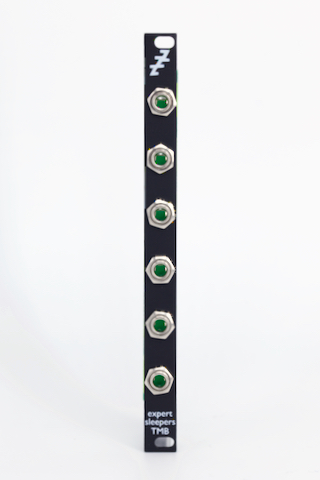
- Panel width: 2HP
- Module depth: 30mm (including cables)
- Current draw: none
In The Box
Pricing & Availablity
The Tiny MIDI breakout is available now.
MSRP: UK £45 (inc VAT), US $TBD (exclusive of sales tax), EU €TBD (exclusive of VAT)
For purchasing links, please see where to buy.
A kit version is available from Thonk, here.
MSRP: UK £45 (inc VAT), US $TBD (exclusive of sales tax), EU €TBD (exclusive of VAT)
For purchasing links, please see where to buy.
A kit version is available from Thonk, here.
Connection Examples
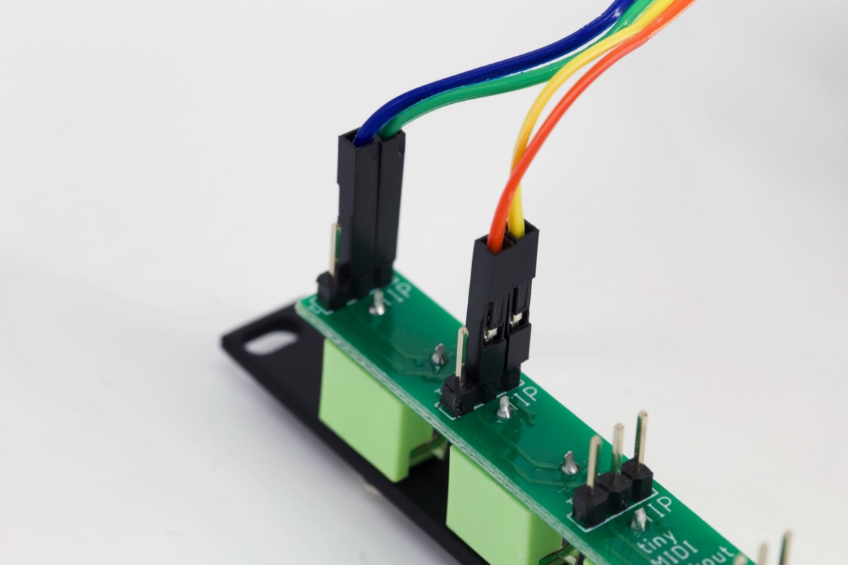
The examples below show the breakout connected with the uppermost socket as the MIDI input and the one below that as the MIDI output, wired for a Type A 3.5mm MIDI cable.
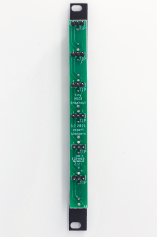
Hold the TMB with its rear facing you. The top of the PCB is the end where the connection header is right on the edge of the PCB. To put it another way, each connection header is above its corresponding jack socket, not below.
Oriented in this way, the jack socket tip is the right pin on the 3-way header, the ring is the centre pin, and the shield is the left pin.
You typically do not need to connect the shield pin.
For type A output, connect pins 1 & 2 from the attached module to the ring and tip pins respectively.
For type A input, connect pins 3 & 4 from the attached module to the tip and ring pins respectively.
For type B, swap ring and tip.
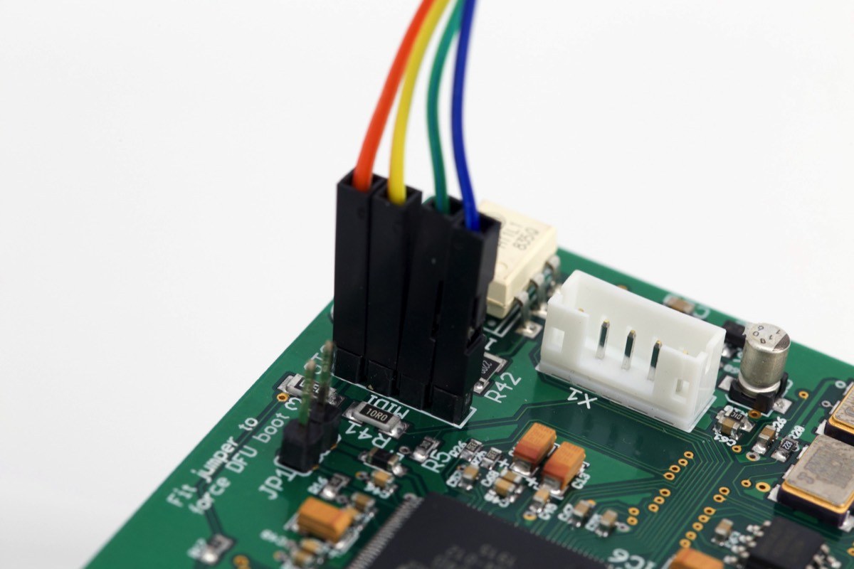
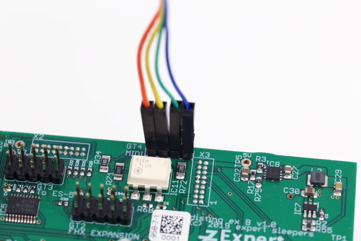
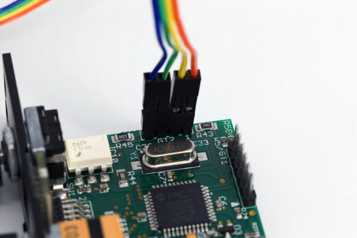
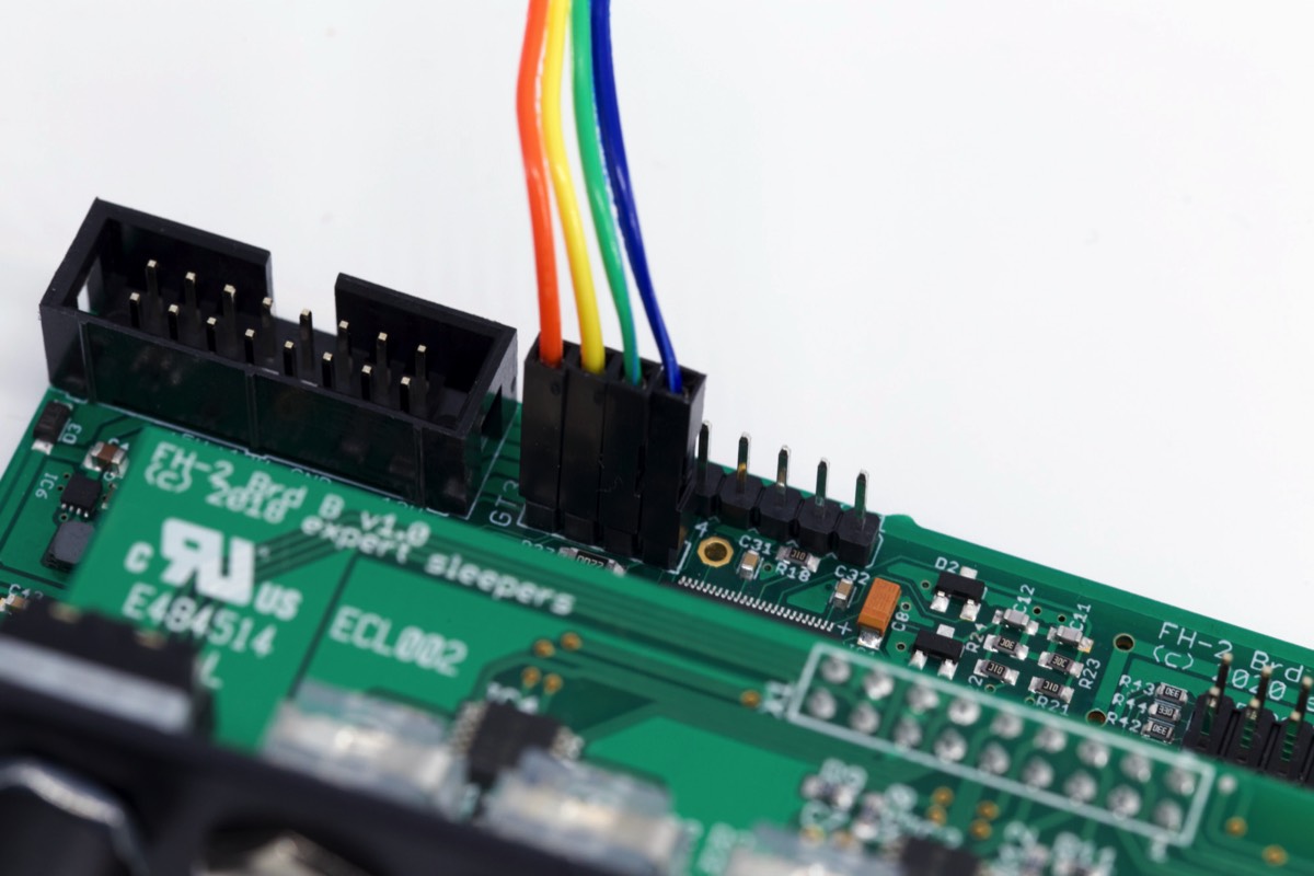
For the disting EX, FH-2, and ES-9, pin 1 is the top pin of the 4-way header. For the disting mk4, pin 1 is the pin closest to the rear of the module.
Hold the TMB with its rear facing you. The top of the PCB is the end where the connection header is right on the edge of the PCB. To put it another way, each connection header is above its corresponding jack socket, not below.
Oriented in this way, the jack socket tip is the right pin on the 3-way header, the ring is the centre pin, and the shield is the left pin.
You typically do not need to connect the shield pin.
For type A output, connect pins 1 & 2 from the attached module to the ring and tip pins respectively.
For type A input, connect pins 3 & 4 from the attached module to the tip and ring pins respectively.
For type B, swap ring and tip.
For the disting EX, FH-2, and ES-9, pin 1 is the top pin of the 4-way header. For the disting mk4, pin 1 is the pin closest to the rear of the module.
Breakout
disting EX
disting mk4
FH-2
ES-9