User Manual
If you have 38 minutes to spare, the video below details all 16 of the disting's functions in turn. Otherwise, each feature has its own little video, further down the page.Installation
House the Disting in a Eurorack case of your choosing. The power connector is Doepfer standard. If using the power cable supplied with the Disting, the red edge of the cable is nearest the bottom of the PCB, and carries -12V. ("-12V" is marked on the PCB itself next to this end of the connector.) Be sure to connect the other end of the power cable correctly, again so -12V corresponds to the red stripe on the cable.Inputs, Outputs and Controls
|
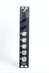
From top to bottom, the disting has
|
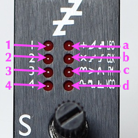
| Below we will refer to the LEDs by name as follows: the left column, from top to bottom, are LEDs 1, 2, 3 & 4; the right column are LEDs a, b, c & d. |
Startup
The sequence is as follows:
- a, b, c, d
- 1, 2, 3, 4
- all 8 at once
- 1 + major version number as binary on a/b/c/d (a is LSB)
- all off
- 1 + minor version number as binary on a/b/c/d (a is LSB)
- 1 + flash a twice
Selecting an algorithm
Don't press the button
On the Disting PCB is a push button. This is used during factory setup and should not be pressed in normal use. If you should happen to press the button while the Disting is powered up, you will need to turn it off and on again to restore normal functionality.The Algorithms
1-a Precision Adder
B = X - Y - offset
offset = ±10V in 1V steps derived from Z
The Z knob/CV sets an offset which is applied to both A and B. The offset is a whole number of Volts. If X/Y are 1V/Octave pitch CVs, Z is therefore an octave shift control. The maximum shift is 10V, positive or negative.
When Z changes, the offset is displayed on the LEDs. While the offset is being displayed, LEDs 1 & 2 both light. After a short while the LED display reverts to showing the current algorithm. The offset is shown as binary on LEDs a-d, with a the least significant bit. If the offset is negative, LED 3 also lights. The patterns on LEDs a-d are as follows ('0' indicates lit, '-' indicates unlit):
| Value | 0 | 1 | 2 | 3 | 4 | 5 | 6 | 7 | 8 | 9 | 10 |
|---|---|---|---|---|---|---|---|---|---|---|---|
| LED a | - | 0 | - | 0 | - | 0 | - | 0 | - | 0 | - |
| LED b | - | - | 0 | 0 | - | - | 0 | 0 | - | - | 0 |
| LED c | - | - | - | - | 0 | 0 | 0 | 0 | - | - | - |
| LED d | - | - | - | - | - | - | - | - | 0 | 0 | 0 |
1-b Four Quadrant Multiplier
B = -X * Y * scale
scale = 1/10 to 10x in steps derived from Z
If for example X is a signal and Y is an envelope, then this algorithm is a VCA. If both inputs are signals, then this is a ring modulator.
The Z knob/CV sets a scale factor which is applied to both outputs. The scale is an integer (whole number) which either multiplies or divides the result, and ranges in value from 1-10.
When Z changes, the scale is displayed on the LEDs. While the scale is being displayed, LEDs 1 & 2 both light. After a short while the LED display reverts to showing the current algorithm. The scale is shown as binary on LEDs a-d, with a the least significant bit. If the scale is a divisor, LED 3 also lights. The patterns on LEDs a-d are as follows ('0' indicates lit, '-' indicates unlit):
| LED 3 unlit | Scale | 1x | 2x | 3x | 4x | 5x | 6x | 7x | 8x | 9x | 10x |
|---|---|---|---|---|---|---|---|---|---|---|---|
| LED a | 0 | - | 0 | - | 0 | - | 0 | - | 0 | - | |
| LED b | - | 0 | 0 | - | - | 0 | 0 | - | - | 0 | |
| LED c | - | - | - | 0 | 0 | 0 | 0 | - | - | - | |
| LED d | - | - | - | - | - | - | - | 0 | 0 | 0 | |
| LED 3 lit | Scale | /2 | /3 | /4 | /5 | /6 | /7 | /8 | /9 | /10 | |
| LED a | - | 0 | - | 0 | - | 0 | - | 0 | - | ||
| LED b | 0 | 0 | - | - | 0 | 0 | - | - | 0 | ||
| LED c | - | - | 0 | 0 | 0 | 0 | - | - | - | ||
| LED d | - | - | - | - | - | - | 0 | 0 | 0 |
1-c Full-wave Rectifier
B = abs( X - Y ) or abs( Y )
Z selects mode
When Z changes, the mode is displayed on the LEDs. While the mode is being displayed, LEDs 1 & 2 both light. 'Independent' mode is indicated by LED 3 lighting; it is unlit in 'combined' mode. After a short while the LED display reverts to showing the current algorithm.
1-d Minimum/maximum
B = max( X, Y )
Z is gate
The Z knob/CV provides a gate function. When Z goes higher than approximately 2.5V, the gate goes high and the outputs follow the inputs according to the min/max relationship. When Z goes below approximately -1.5V, the gate goes low and the outputs are frozen.
When the gate changes state, it is displayed on the LEDs. While the gate is being displayed, LEDs 1 & 2 both light. The state of the gate is reflected in LED 3. After a short while the LED display reverts to showing the current algorithm.
2-a Linear/Exponential Converter
B = log2( Y / scale )
Z is Hz/V scale, centred on 1kHz
Input X is the exponential input; its corresponding linear output is A. Y is the linear input, whose exponential output is B.
Z sets the scale factor which is common to both conversions. It sets the number of Hz per Volt, with arrange from near zero to about 2kHz. The Yamaha CS-15, for example, uses about 1100Hz/V, which is about half way on the Z knob here.
The zero Volt point on the exponential scale used is C3 (approximately 130.81Hz).
2-b Quantizer
B = trigger on note change
Z chooses scale & function of Y
Y = transpose (Z positive) or trigger (Z negative)
As well as providing a chromatic scale, this algorithm can also constrain the quantized values to a musical scale or chord. This is controlled by the Z knob/CV.
When Z changes, the scale is displayed on the LEDs. While the scale is being displayed, LEDs 1 & 2 both light. After a short while the LED display reverts to showing the current algorithm. The patterns on LEDs a-d are as follows ('0' indicates lit, '-' indicates unlit):
| Scale | chromatic | major scale | minor scale | major triad | minor triad | root +5th | major triad +6th | minor triad +6th | major triad +7th | minor triad +7th | root +5th +6th | root +5th +7th | pentatonic major | pentatonic minor |
|---|---|---|---|---|---|---|---|---|---|---|---|---|---|---|
| LED a | - | 0 | - | 0 | - | 0 | - | 0 | - | 0 | - | 0 | - | 0 |
| LED b | - | - | 0 | 0 | - | - | 0 | 0 | - | - | 0 | 0 | - | - |
| LED c | - | - | - | - | 0 | 0 | 0 | 0 | - | - | - | - | 0 | 0 |
| LED d | - | - | - | - | - | - | - | - | 0 | 0 | 0 | 0 | 0 | 0 |
When Z is positive input Y is a transpose control. The CV on input Y is quantized (to a chromatic scale) and added to output A (after input X has been quantized to the chosen scale).
When Z is negative input Y is a trigger. In this mode, input X is only sampled and converted to a new quantized value when input Y rises over approximately 1V. (In non-triggered mode, X is constantly sampled and a new note is output as soon as X moves into the next semitone range.)
2-c Comparator
B = inverted gate
Z is hysteresis
The Z knob/CV input sets the hysteresis (for an explanation of hysteresis see here). It has an approximately 0-10V range. Negative values are clamped at zero.
2-d Dual Waveshaper
B = triangle-to-sine Y
Z is gain
Input X/output A provide what is usually termed a wavefolder. This increases the harmonic content of the sound in interesting ways, especially as the gain changes.
Input Y/output B provide a triangle-to-sine waveshaper. Used on most audio this is a relatively gentle form of overdrive/saturation. However, when fed with the right level of triangle wave, the output is exactly a sine wave, which is useful when you have a triangle wave VCO handy but really want a pure sine wave instead.
3-a Sample and Hold
B = noise ±8V
Z is slew rate
Output B is a white noise signal, with range ±8V. A noise signal is commonly fed into the input of a sample and hold device to generate clocked random voltages.
The Z knob/CV controls the slew rate of output A. At the minimum value of Z, changes in A are instantaneous. As Z increases, changes in A take place more slowly.
3-b Slew Rate Limiter
B = log slew rate limited ( X + Y )
Z is slew rate
The Z knob/CV controls the slew rate for both outputs. At the minimum value of Z, changes are very rapid. As Z increases, changes take place more slowly.
3-c Pitch and Envelope Tracker
B = envelope dervied from X
Z is slew rate for envelope
Output A is a 1V/octave pitch CV reflecting the pitch of the signal on input X. The 0V point is C3 (approximately 130.81Hz). Input Y is simply added to the pitch CV, providing a means of applying e.g. vibrato, or transposition.
Output B tracks the envelope of the signal on input X. It goes to zero when the algorithm fails to track a pitch.
Knob/CV Z sets the slew rate of the envelope, controlling how quickly it tracks changes in level. At the minimum value of Z, changes can be very rapid, which may produce undesirable effects, especially if pitch tracking is not working well. As Z increases, changes take place more slowly.
3-d Clockable Delay/Echo
Y is clock input
Z is feedback
A = dry + delay in ratio according to feedback
B = delay signal only
Input X is the signal input. Any audio signal can be fed in here.
Input Y is the clock input. Any clock pulse in excess of 1V can be used. The time between rising trigger edges is used to set the delay time. If the time between triggers is greater than the maximum delay time, the time is divided by two until it is small enough. This way, you always end up with a rhythmically useful delay time.
The Z knob/CV controls the feedback, from zero to slightly more than 100%.
Output A is a mix of the dry (undelayed) signal and the delay effect. The amount of delay in the mix rises in direct proportion to the amount of feedback.
Output B is the delayed signal only. Use this and the input signal, plus an external mixer, if you need more flexibility in the dry/wet balance than is offered by output A.
4-a LFO
Y is waveshape
Z is tune
A is saw -> sine -> triangle
B is pulse -> square -> pulse
Input X is a Hz/V frequency control, scaled at 1Hz/V. Note that the input is allowed to go negative, resulting in a phase-reversed output.
Knob/CV Z is a tuning control, with a range of approximately ±10Hz. This is simply added to the setting from input X (so with input X disconnected, the knob can be used to manually set an LFO rate).
Input Y controls the waveshape of the output signals. Signals in the range ±10V give the full range of possible waveshapes:
| Input Y | -10V | 0V | +10V |
|---|---|---|---|
| Output A | saw | sine | triangle |
| Output B | 0% duty cycle pulse | 50% duty cycle pulse (square) | 100% duty cycle pulse |
4-b Clockable LFO
Y is waveshape
Z is integer multiplier/divider
A is saw -> sine -> triangle
B is pulse -> square -> pulse
Input X is the clock input. Any clock pulse in excess of 1V can be used. The time between rising trigger edges is used to set the cycle time.
Input Y controls the waveshape of the output signals. Signals in the range ±10V give the full range of possible waveshapes:
| Input Y | -10V | 0V | +10V |
|---|---|---|---|
| Output A | saw | sine | triangle |
| Output B | 0% duty cycle pulse | 50% duty cycle pulse (square) | 100% duty cycle pulse |
When Z changes, the scale is displayed on the LEDs. While the scale is being displayed, LEDs 1 & 2 both light. After a short while the LED display reverts to showing the current algorithm. The scale is shown as binary on LEDs a-d, with a the least significant bit. If the scale is a divisor, LED 3 also lights. The patterns on LEDs a-d are as follows ('0' indicates lit, '-' indicates unlit):
| LED 3 unlit | Frequency | 1x | 2x | 3x | 4x | 5x | 6x | 7x | 8x | 9x | 10x | 11x | 12x | 13x | 14x | 15x | 16x |
|---|---|---|---|---|---|---|---|---|---|---|---|---|---|---|---|---|---|
| LED a | 0 | - | 0 | - | 0 | - | 0 | - | 0 | - | 0 | - | 0 | - | 0 | - | |
| LED b | - | 0 | 0 | - | - | 0 | 0 | - | - | 0 | 0 | - | - | 0 | 0 | - | |
| LED c | - | - | - | 0 | 0 | 0 | 0 | - | - | - | - | 0 | 0 | 0 | 0 | - | |
| LED d | - | - | - | - | - | - | - | 0 | 0 | 0 | 0 | 0 | 0 | 0 | 0 | - | |
| LED 4 | - | - | - | - | - | - | - | - | - | - | - | - | - | - | - | 0 | |
| LED 3 lit | Frequency | /2 | /3 | /4 | /5 | /6 | /7 | /8 | /9 | /10 | /11 | /12 | /13 | /14 | /15 | /16 | |
| LED a | - | 0 | - | 0 | - | 0 | - | 0 | - | 0 | - | 0 | - | 0 | - | ||
| LED b | 0 | 0 | - | - | 0 | 0 | - | - | 0 | 0 | - | - | 0 | 0 | - | ||
| LED c | - | - | 0 | 0 | 0 | 0 | - | - | - | - | 0 | 0 | 0 | 0 | - | ||
| LED d | - | - | - | - | - | - | 0 | 0 | 0 | 0 | 0 | 0 | 0 | 0 | - | ||
| LED 4 | - | - | - | - | - | - | - | - | - | - | - | - | - | - | - | 0 |
4-c VCO with linear FM
Y is linear FM input
Z is tune ±0.5 octaves
A is sine
B is saw
The 0V point for the pitch input is C3 (approximately 130.81Hz).
The Z knob/CV provides a tuning control, with a range of approximately ±0.5 octaves.
The A and B outputs provide sine and saw waves respectively, with an amplitude of ±8V (16V peak-to-peak).
4-d VCO with waveshaping
Y is waveshape/PWM
Z is tune ±0.5 octaves
A is saw -> tri -> saw
B is pulse -> square -> pulse
The 0V point for the pitch input is C3 (approximately 130.81Hz).
The Z knob/CV provides a tuning control, with a range of approximately ±0.5 octaves.
Input Y controls the waveshape of the output signals. Signals in the range ±10V give the full range of possible waveshapes:
| Input Y | -10V | 0V | +10V |
|---|---|---|---|
| Output A | saw (falling) | triangle | saw (rising) |
| Output B | 0% duty cycle pulse | 50% duty cycle pulse (square) | 100% duty cycle pulse |