User Manual
Software
Please proceed to the downloads page to download the Silent Way software, and its user manual.
ES-5
Please refer to the image below (click to enlarge):

Installation
House the ES-5 in a Eurorack case of your choosing. The power connector is Doepfer standard. If using the power cable supplied with the ES-5, the connector is keyed and will only insert into the ES-5 the correct way round, in which case the red edge of the cable is nearest the edge of the PCB, and carries -12V. ("-12V" is marked on the PCB itself next to this end of the connector.) Be sure to connect the other end of the power cable correctly, again so -12V corresponds to the red stripe on the cable.
The ES-5 also needs to be connected to a host module, via its header marked GT7 ("To ES-3/8" on the current version, or just "To ES-3" on older units). Exactly how this happens depends on the module:
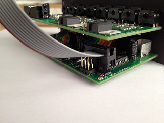
ES-3 mk3/mk4, ES-8, ES-9, disting EX, or disting NT - connection is via the supplied 10-way cable to the header on the ES-3/ES-8/ES-9/disting EX/disting NT PCB (see image below for ES-3; refer to the relevant user manual for the other modules).
ES-3 mk2 - connection is via the supplied 10-way cable to the header on the ES-3 mk2 PCB (see image below). You may find it helpful to loosen the screws that attach the PCB to the module's panel while fitting the cable. Note that the six conductors on the side of the cable with the red stripe engage with the 6-way header on the ES-3; the four unused conductors hang over the small IC at the edge of the board.
ES-3 mk1 - requires an equivalent connection to be soldered to the ES-3 PCB. See here.
Jumpers
Below the connector for the input from the ES-3 is a header fitted with a jumper. This determines which of the ES-3's four stereo pairs will drive the ES-5. In the factory-fitted position as shown in the photo above, the ES-3's fourth pair (i.e. channels 7 & 8) is used. This corresponds to the jumper position labelled '2' on the PCB. Positions 3-5 correspond to ES-3 channels 5/6, 3/4 and 1/2 respectively.
When using the ES-5 with an ES-9, this jumper must be in the factory-fitted position.
Connecting Expansion Modules
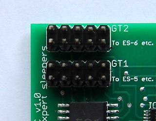
The ES-5 has 6 connectors for expansion modules such as the ESX-GT Gate Expander. Please turn the power off before connecting or disconnecting the expansion modules.
Note that the header for channel 1 carries the same signals as the ES-5's own output jacks, so when connecting expansion modules, you might like to use channels 2 and up.
The 6 channels are derived from the incoming stereo audio stream as follows - channels 1/2/3 are derived from the left channel, and channels 4/5/6 are derived from the right channel. Therefore if for example you only use channels 1/2/3 you are free to use the right channel (by default, ES-3 channel 8) as normal without affecting the ES-5's operation.