User Manual
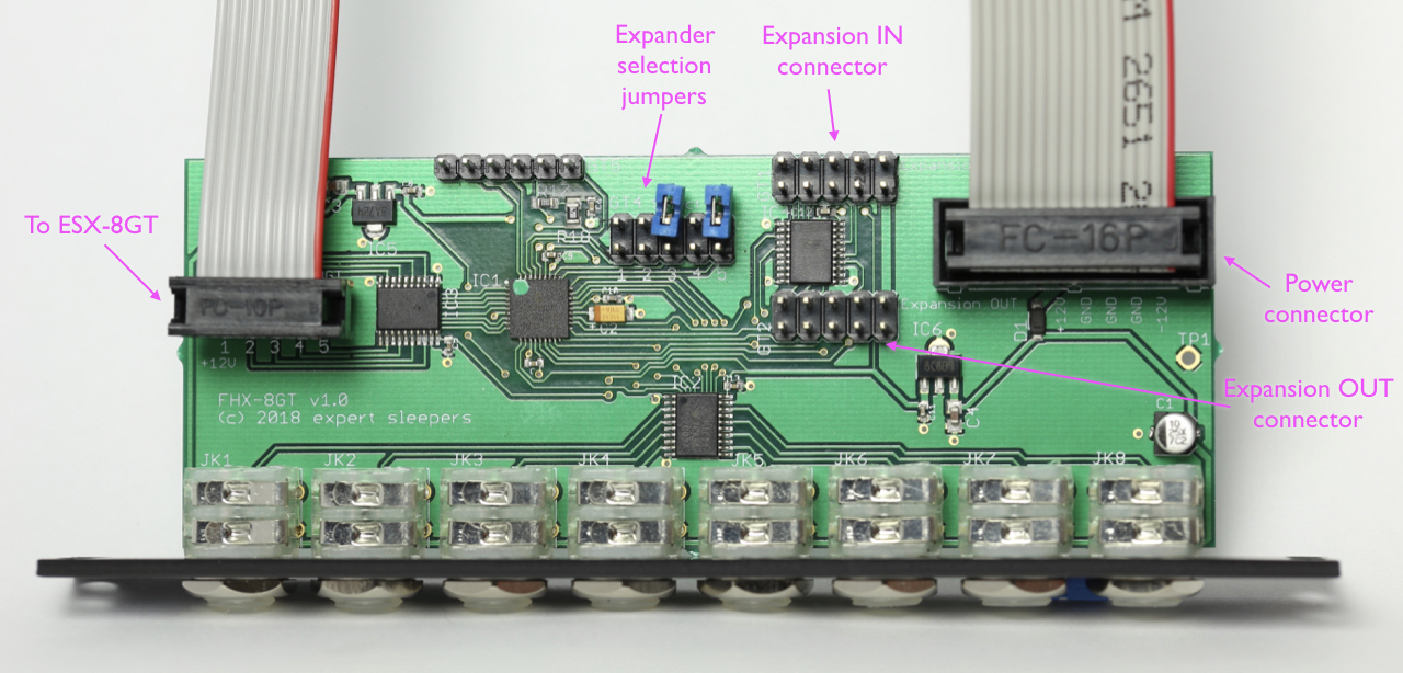
Please refer to the image below:
Installation
Power
House the FHX-8GT in a Eurorack case of your choosing. The power connector is Doepfer standard. If using the power cable supplied with the FHX-8GT, the connector is keyed and will only insert into the FHX-8GT the correct way round, in which case the red edge of the cable is nearest the edge of the PCB, and carries -12V. ("-12V" is marked on the PCB itself next to this end of the connector.) Be sure to connect the other end of the power cable correctly, again so -12V corresponds to the red stripe on the cable.
Connection to FH-2
The FHX-8GT also needs to be connected to an FH-2 module via its "Expansion IN" connector. A 10-way cable is supplied with the FHX-8GT. Orient this cable with the red stripe down at both ends.
Note: while the 10-way connector on the FHX-8GT may look like the power connector on some Doepfer modules, it is not wired the same. If you connect this to a Doepfer power bus, you will almost certainly fuse the power supply and fry the FHX-8GT. This connector is only to be used for connecting the FHX-8GT to an FH-2.
Multiple expanders
When multiple FHX-8GTs are to be driven from a single FH-2, they are daisy-chained. The first connection is from the FH-2 to the first FHX-8GT's Expansion IN connector. The second connection is from the first FHX-8GT's Expansion OUT connector to the second FHX-8GT's Expansion IN connector. Further FHX-8GTs are connected in the same manner. All the expansion cables are oriented the same way - if you find yourself twisting the cables, chances are you're inserting the ends incorrectly. With a row of FH-2/FHX-8GTs, all the cables should stay flat.
The above also applies when combining the FH-2 and FHX-8GTs with the FHX-8CV expander. The expansion modules are daisy-chained from the OUT header on one to the IN header on the next.
Note that each FHX-8GT requires its own individual power connector as well as the expansion connector.
Connection to ESX-8GT
Each FHX-8GT can also be expanded with an ESX-8GT. Use the 10-way cable provided with the ESX-8GT to connect to the header on the FHX-8GT marked "GT3 To ESX-8GT". As usual, the red stripe is down, as in the photograph above and in the ESX-8GT user manual.
Jumpers
Expander selection jumpers
The header on the PCB marked "GT4 Select" is used to set which expander number the FHX-8GT responds to. Up to four FHX-8GTs can be connected to an FH-2, so there are four possible combinations of jumpers.
The expansion channel is selected by placing jumper links in a binary pattern on positions 2 & 3 of the header. As shipped, both jumpers are in the 'off' position, corresponding to expander number 0. (Note the jumpers themselves might be shipped in any 'off' position, simply for storage. In the photo above, they are on positions 3 & 5.)
| Jumper 2 | Jumper 3 | FH-2 output numbers | FH-2 output numbers of attached ESX-8GT | |
|---|---|---|---|---|
| Expansion number 0 | off | off | 65-72 | 73-80 |
| Expansion number 1 | off | on | 81-88 | 89-96 |
| Expansion number 2 | on | off | 97-104 | 105-112 |
| Expansion number 3 | on | on | 113-120 | 121-128 |